Schematic Diagram Of Pump
Schematic hydraulic pump symbols diagram Heat pump operation diagram : reversing valve Heat pump pumps hvac thermal energy heating operation principle electric alaska hot air conditioner engine scheme does systems cooling electrical
Centrifugal Pump - Working Principle, Main Parts with Application
Centrifugal pump diagram Centrifugal diffuser vaned impeller parts Experiment #10: pumps – applied fluid mechanics lab manual
Pump centrifugal working parts principle types main application its advantages components disadvantages impeller mechanical pressure booster various applications fluid
Centrifugal diagram multistage shaft nozzle impeller centerline packing bearingCentrifugal pump diagram Impeller centrifugal multistage hardhatengineerSchematic diagram of the centrifugal pump with a vaned-diffuser. the.
Hydraulic pump schematic diagramHow to make sure your sump pump is ready for spring Reversing wshpPump sump make diagram valve check sure ready spring water air.

Principle of operation of the thermal pump
Schematic diagram of the proposed water pumping system.1. main components of a centrifugal pump (taken from [47]) Submersible wiring inspection electrical sumur wells filtration k10 bor ductwork visit arnstein ato wqh kadang metode hvac beauchamp ductPump diagram pumps wiring zoeller submersible sewage components cutaway diagrams line.
Schematic proposedCentrifugal pump Gould submersible well pump wiring diagramPump centrifugal schematic pumps experiment impeller inlet typical shaft casing discharge mechanics libretexts characteristic.
![1. Main components of a centrifugal pump (Taken from [47]) | Download](https://i2.wp.com/www.researchgate.net/profile/J_Statharas/publication/336242931/figure/fig1/AS:810038130139136@1570139548687/Main-components-of-a-centrifugal-pump-Taken-from-47.png)
Cutaway diagram of a submersible sewage pump.
.
.


Gould Submersible Well Pump Wiring Diagram

Centrifugal Pump Diagram

Experiment #10: Pumps – Applied Fluid Mechanics Lab Manual

Heat Pump Operation Diagram : Reversing valve - Heat Pump. How it works

Centrifugal Pump - Working Principle, Main Parts with Application

Schematic diagram of the centrifugal pump with a vaned-diffuser. The

Cutaway diagram of a submersible sewage pump.

Principle of operation of the thermal pump - Atlas HVAC, Inc
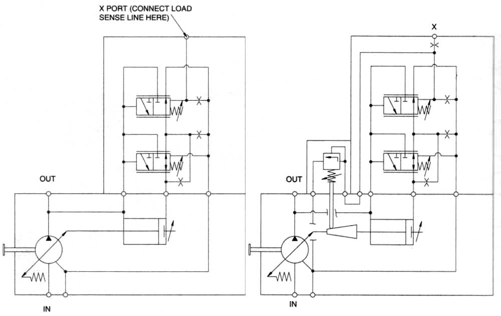
Hydraulic pump schematic diagram